VIV Solutions® has conducted a calibration exercise using data obtained from a controlled experiment with well-known directly-measured inputs. Results from this test program are presented alongside trendlines generated using either SHEAR7’s default input coefficients[i] or new coefficients recommended by VIV Solutions, respectively. The information is applicable for Reynolds numbers ranging from 150,000 to 360,000, which is representative of most production risers and large umbilicals. Values can also be extrapolated for higher Reynolds numbers applications such as tendons or drilling risers with a moderate level of confidence.
The ultimate objective this endeavor was to produce a better method for modeling VIV Solutions’ suppression devices in SHEAR7. In recent years, we have made significant enhancements to our products to further improve their robustness and performance in the field. We have also endeavored to design products that better match the test data for which this calibration exercise is based. As such, the calibration information presented herein is strictly for use with VIV Solutions’ helical strakes and fairings. This is especially important for fairings since small changes in design or geometry can significantly impact their performance.
Raw test data was collected by four bi-axial accelerometers, with accelerometers 1 and 2 located near the low-velocity inner end of a linear sheared flow and accelerometers 3 and 4 at the high-velocity outer end. For the datasets utilizing suppression devices, the strakes or fairings were installed at the outer end of the pipe since this is most representative of field conditions where current speeds are highest near the top of the water column.[ii],[iii]
The following comments should be carefully considered before attempting any modeling in SHEAR7:
- A smooth tubular was used during testing to generate the measured datasets. In the field, a build-up of marine growth will likely render a suppression device less effective. (Input parameter values for fouled tubulars may be provided by VIV Solutions in the future.)
- The plots were generated using data from isolated tubulars in a low turbulence environment. Tandem or offset tubulars may experience different vibration and suppression performance relative to that of isolated tubulars.
- Many of the coefficients used in SHEAR7 are rounded to the nearest 0.05 or 0.1 value. Since adjustments to input parameters only produce minor changes in the response predictions, no further effort was undertaken to refine the values at this time.
- Some of the parameters may not make complete physical sense. In the past, this was done intentionally to keep the results conservative and adequately robust. (For example, the reduced velocity damping coefficient for the bare riser condition is 0.0.) In general, it should be noted that the coefficients derived from this exercise have an improved physical basis relative to the default values, especially in the common.CL files for fairings and helical strakes.
- The helical strake calibration requires different values for the bare tubular portion than a completely bare tubular or a bare section of a tubular with fairings. This is like attributable to helical strakes’ ability to influence damping, correlation length, and vortex input frequencies, although the physical basis for this is not entirely understood.
- The data assumes that all regions of the tubular experiencing current velocities greater than 60% of the maximum current value are covered with VIV Solutions’ helical strakes or fairings. For example, a 1,000-meter tubular with a monotonically-varying sheared current profile of 3 m/sec at the surface would be covered with suppression devices beginning at the MWL to a water depth at which the current no longer exceeds 60% of the surface value (1.8 m/sec). Furthermore:
- For helical strakes, a minimum suppression coverage density of 85% is required (allowing some gaps for appurtenances, field joint coatings, etc.).
- For fairings, a minimum suppression coverage density of ~70-75% is required (allowing some gaps for appurtenances, field joint coatings, etc.).
- Some calibration work was attempted for reduced coverage lengths but the results were not always conservative, therefore the revised coefficients are unlikely to produce conservative results when lower coverage lengths or coverage densities than those stated above are used.
- Stress concentration factor inputs for the tubular are subject to the user’s discretion and are design dependent. It may be appropriate to divide various regions (i.e., those with suppression) into multiple regions to properly address the stress concentrations.
- Safety factors should be employed during a VIV analysis, whether by increasing the stress concentration factor, utilizing a conservative fatigue curve, applying a safety factor to the fatigue damage rate, or a combination thereof. This is especially important when performing an extreme event analysis (i.e., 100-year current).
- For higher harmonics, the program defaults were utilized during the calibration exercise. This is an area of ongoing industry research. The user may want to consider even more conservative input values for higher harmonics, especially for structures that are tension-dominated at the modes of greatest concern.
It should be noted that this data is not meant to be a definitive calibration but rather an improvement in the overall understanding of SHEAR7 and its use in modeling VIV.
Future calibrations efforts require knowledge of suppression length coverage density and length to better predict spanwise correlation and suppression device damping. VIV Solutions endeavors to undertake this exercise at the request of interested clients.
[i] User Guide for SHEAR7 Version 4.10a, January 2018.
[ii] Allen and Liapis (2014), The Effect of Coverage Length and Density on the Performance of Helical Strakes, OMAE2014-23107, Proceedings of the ASME 2014 33rd Annual International Conference on Ocean, Offshore and Arctic Engineering, June 8-13, 2014, San Francisco.
[iii] Allen and Liapis (2014), The Effect of Coverage Length and Density on the Performance of Fairings, OMAE2014-23108, Proceedings of the ASME 2014 33rd Annual International Conference on Ocean, Offshore and Arctic Engineering, June 8-13, 2014, San Francisco.

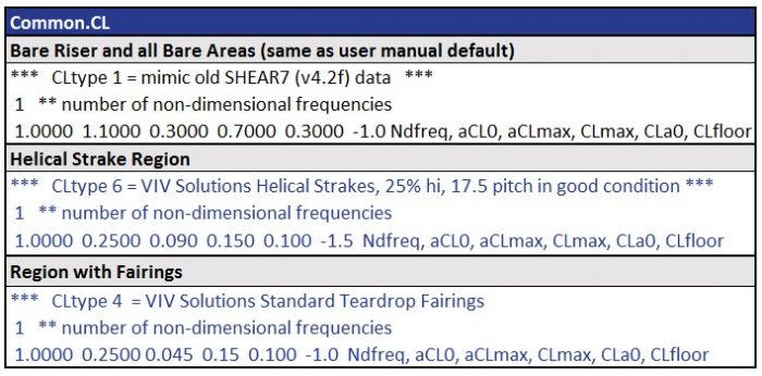
 Figure 1 – Long Bare Pipe Data Using SHEAR7 Default Coefficients


